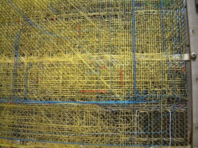
Wirewrap Computer Backplane
Shortly after the New Year Bjorn Dahlberg delivered the MIP. Corinne Robinson and Dave Yonamine were making good progress on the Display Terminal software. Bjorn worked directly with the Corinne and Dave debugging the MIP/Display Console in our lab, but we were only a week away from having the first prototype, so we decided not to hook the Console up to the Breadboard, as it was being used extensively by software engineering. We wanted them to catch up on the schedule.
On a Monday morning at the end of January of 1980 the first two B5900 prototypes built by manufacturing were wheeled into our lab. There was great anticipation. The first thing was to connect the Display Terminal/MIP to the machine and begin debugging the maintenance path. A few problems were found, but Dave Eaves and Al Regalato made quick work of it. I remember Bjorn only had to come in for a day or so, and all was functioning. We began to load test vectors. A couple of days later Jerry came into my office with a serious look on his face. He said, “Jack, we have a problem. The flip-flop level testing seems to work fine, but the microcoded register level tests do not seem to work reliably. They may pass one test run, and then fail the next run. “ A register level test was a simple test of the 2901 data path. For example, the firmware would load the number 1 in register 1, and the number 2 in register 2, and then add the registers to get the number 3 in register 1. Sometimes this would work, and sometimes it would not. These tests worked flawlessly on the breadboard. So what was the problem? As the designer of the DP, I was called to debug again. Jerry and I worked together. My thought was the problem had something to do with either timing, or noise (sometimes called crosstalk) of the signals. The 2901 was self contained, so the error could not be there. We looked at the signals feeding the 2901. What we saw was that the command bits to the 2901 would change part way through the clock cycle. What started out as an ADD instruction changed to a SUBTRACT for a brief time, and then back to an ADD. Depending on the timing, the 2901 might execute the ADD, or the SUBTRACT, giving the answer 1, instead of 3.
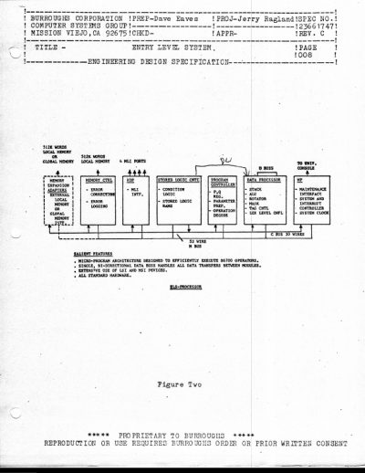
Now we knew what was happening, but the question was why? We began tracing the signals back to their source. The instruction to the 2901 came from the SLC. The SLC consisted of the microcode memory and sequencer, and a 30 bit command register. The instruction came out of the SLC memory and was clocked into a 30 bit register at the beginning of the machine cycle. The register drove the 30 bit C (or command) bus on the backplane that went to every card. The DP interpreted the commands directed to it.
We checked the SLC, and it worked flawlessly, the right command was in the C register. We traced the signal and found the problem. The breadboard used wires to transmit the signals to the edge connector that plugged into the backplane. The prototype used circuit etching. The breadboard wire resistance was much lower than the prototypes, and very close to that of the backplane. On the other hand, the resistance of the circuit etch was much higher than the backplane. When the signal hit the backplane connector on the circuit card, part of it bounced back, causing a reflection. The reflection is what caused the signal disturbance as it propagated across the backplane to the DP. How were we going to fix this? Basically, nothing in the B5900 prototype worked because all the C bus commands to the different parts of the machine were corrupted by these reflections.
I called an emergency meeting with the circuit’s engineers. They spent a couple of weeks observing and measuring, and confirmed what Jerry and I found. They explained that UIO used much slower bus speeds than the B5900. We exceeded the design specs for the hardware we were using, one of the tradeoffs of not having an approved project. They suggested we insert something called a ground plane in the circuit boards under the edge connectors. This was a minor change since the boards already had a ground plane under the IC’s and main part of the circuit board. They also suggested some changes to the signal routing and etch size on the backplane. I asked them is this would guarantee reliable operation? They said no, they could not guarantee that the design would be reliable without a complete redesign of the edge connector/backplane interface. I was dumbfounded; such a change would take almost a year. We needed another solution.